-
Can you run self diagnosis with that ecu?http://z31performance.com/showthread…2-2-(-now-NA2T
My build thread (: -
Good question. I wish I had as good an answer. I don't recall anything about JWT ECU's having self diagnosis, but I will be trying this series of tests. (It includes the CAS among others.) -
The CAS is what tells the coil to send a spark to the cap. Seriously, pull the distributor and spin it with the key on. If the injectors click and no spark it's something else. If you get no spark and no injectors clicks then it's the CAS.Prius… because Pretentious wouldn't fit across the back of the car…
Cheap, Fast, Reliable - pick any two
My 1986 Turbo Build -
OK … will try that tomorrow and give an update on results.
Thanks for all the suggestions.
-
Distributor has spun …
Well, it certainly sounded like the injectors were clicking (and squirting?) as I rotated the rotor by hand with the unit out of its gear. I guess this means it's the PRW-2 module, eh?
PS: I made a mark on the distributor's inner shield relative to the rotor's initial location and re-inserted it so that it was in the exact same spot. Is it possible since the crank angle sensor is in the distributor head, that it's 360 degrees off? … given that the crank rotates 720 degrees for every 360 for the distributor. Does it matter? I didn't count how many rotations I made with the rotor. (Insert Homer Simpson DOH) -
You should set the engine to tdc on cylinder 1 and just install the distributor per the fsm. To rule out the possibility of it being installed incorrectly to begin with.http://z31performance.com/showthread…2-2-(-now-NA2T
My build thread (: -
did you happen to check the secondary side of the coil. -
Here are resistance values for the coil and ignition module (PRW-2):
Primary input - Primary return = 1.3 ohms
Primary input - Chassis Ground = Infinite
Primary return - Chassis Ground = Infinite
Primary input - Secondary output = 9.17 kOhms (9170 ohms)
Primary return - Secondary output = 9.17 kOhms (9170 ohms)
Secondary output - Chassis Ground = Infinite
PWR-2 Ground - Chassis Ground = 5.3 ohms (not a perfect ground, but should not be the issue)
So basically, the coil is isolated from the chassis; no shorting to ground. Both the primary input and return against the secondary output are the same, which is expected given that the coil is technically an autotransformer. Anyway, everything seems to be within spec. -
Correct me if im wrong but primary positive and secondary positive should be open only the ground from primary and secondary should utilize the same connection
if you are getting a closed circuit from primary + to secondary + then I would say you have a bad coil -
Ooops, I believe you're right. It was late when I took the readings (I'm in NJ, as my name suggests).
Going to check again and get back to you --- but if my numbers were correct, then I do have a bad coil. -
1408547770809.jpg
Sorry I have that backwards primary and secondary + share the same connection, primary - and secondary - should be open -
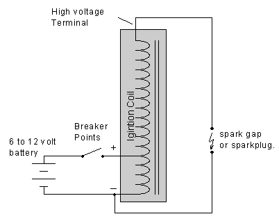
On second/third thoughts I'm not so sure about your comments above (and my previous Ooops comment). Both the Primary positive and Primary return (negative on primary) do go to the Secondary output (from coil to the plug), but differ only by the primary's internal resistance, in my case 1.3 ohms. (That's why the meter showed basically the same 9.17kohms for each --- too small a measurable difference on that scale.) Look at your diagram (and mine from 2 comments ago). An ohmmeter placed between the switch and the end of the primary (primary negative) and the output of the secondary (before the plug) will see the majority (99.99%) of resistance through the secondary; continuity is achieved by going in reverse through the primary. However, compared to the secondary, the primary winding is like a piece of wire. (Remember, it's in some ways an Autotransformer, not a basic transformer.) About 10 amps or so will flow through the primary yet none through the secondary since the spark plug gap makes it an open DC circuit --- this basically makes the battery's current negligible in the secondary, essentially isolating it. This then allows the secondary's windings to charge accordingly to the turns ratio between the two (primary/secondary). The "switch" is in the ECU as I pretty much thought from the beginning. -
Ok I see what you are saying. Shouldn't you be getting more than 9.17k ohms if you are going from primary return to secondary return or if that is through both windings then you should have less than 9.17k ohms in the secondary windings.
Shouldn't you be getting three different readings
primary
secondary
primary+secondary
sorry if im making this confusing this helps me learn a thing or too.
-
The difference is going to be the internal resistance of the primary, which is only 1.3 ohms ---- so you are correct in that there will be different resistances. But take note that when using the kilo-ohm scale, a mere 1.3 ohms won't show up. It's no different that a piece of ordinary wire attached. Negligible. It's 9170 vs. 9171.3 ohms. -
Ok I see that does make sence
You might be right about the prw-2 then

Copyright © 2006–. All rights reserved. Privacy Policy